


0
The figure below whose corners are labelled ABCD could represent the vector diagram for a Hamilton-Russell traction system if the lines were the correct length and an arrow pointing in the correct direction was drawn on them. Which of the following modifi cations to the diagram would make it more closely resemble the correct diagram?
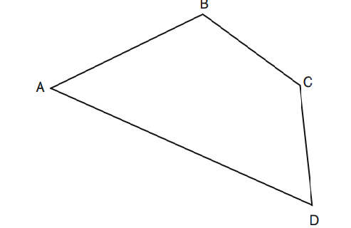
- The three lines D to C, C to B and B to A should be the same length and an arrow pointing from D to A should be drawn on the fourth line.
- Arrows should be drawn so that their directions describe an anticlockwise circuit and the line A to D should be the longest.
- The resultant traction force is represented by the vector from C to B and should be longer than the other three lines.
- All four lines should be the same length and the vector directions are from D to C, from C to B, from B to A, and from A to D.
 Medicine
A: The three lines between D-C, C-B, B-A should be the same length as they are all the same force in three cords. They add to form the resultant (traction) vector from D to A.
need an explanation for this answer? contact us directly to get an explanation for this answer